


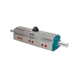


3-Position Pneumatic Actuator
Engineered for multi-stage liquid filling, batching, and flow-diverting systems. Delivers precise open, intermediate, and closed valve control to eliminate line shock and material overflow.
3-Position Pneumatic Actuator
Item Number: HPA series
- Rotation: 0°–45°–90° / 0°–90°–180° (Adjustable intermediate stop)
- Actuator Type: Double Acting (DA) & Spring Return (SR)
- Housing Material: Hard Anodized Extruded Aluminum
- Seal Material: NBR (Viton / Silicone optional)
- Torque Output: DA: 20–1,923 Nm | SR: 8.5–827 Nm (@ 5 bar)
- Air Supply Pressure: 2–8 bar
- Temperature Range: Standard: -20°C to +80°C | Low Temp: -35°C to +80°C | High Temp: -15°C to +150°C
- Air Supply: Filtered, Dry Or Lubricated
- Mounting Standard: ISO 5211 & NAMUR VDI/VDE 3845
- Certificates:ISO 9001, CE, ATEX, SIL3, EAC and IP67


Quote Now
Get Free Catalog
Custom Actuator Housing Color
We customize 3-position pneumatic actuator housing colors (RAL/Pantone) with durable epoxy powder coating to match your corporate brand identity, system color-coding, or specific project aesthetic requirements.
Custom OEM Label
We offer private label 3-position pneumatic actuator solutions for distributors and OEM valve makers. Choose corrosion-resistant metal plates (stainless/aluminum) with laser-etched logos, or high-tack weatherproof industrial stickers.
18-Month Factory Warranty
Every 3-position pneumatic actuator includes an 18-month warranty from the shipment date, providing a 6-month buffer beyond industry standards for ocean transit, customs clearance, and warehouse stocking.
Description of HPA Series 3 Position Pneumatic Rotary Actuator
The 3-position pneumatic actuator available in standard 0°–45°–90° and 0°–90°–180° configurations, offered in both Double Acting (DA) and Spring Return (SR) options. Built-in auxiliary pistons stop the main rack at a set middle angle. By splitting valve travel into fast filling and slow shut-off steps, it protects pumps and flow meters from sudden line shock while keeping filling cycles short.
Specifications & Features
100% Repeatable Mechanical Stop: Internal auxiliary pistons physically block the main pistons at the middle angle. Because it stops against a solid mechanical bolt rather than balanced air pressure, the valve will not drift from pipe vibration or supply pressure drops.
Externally Adjustable Mid-Angle: Outside travel bolts let technicians adjust the middle stop angle, but only upward (above 45° or 90°). If your application requires a smaller angle (such as 20° or 30°), please let us know when ordering so we can set it at the factory.
Independent End-Stroke Adjustment: Independent stop screws provide ±5° travel adjustment at both fully closed (0°) and fully open positions (90° or 180°), allowing maintenance teams to set exact disc seating on-site for tight shut-off.
Prevents Pipe Shock and Tank Overflow: Allows fast bulk filling at full open, then drops to a low flow rate at the middle stop before final shut-off. This two-stage action prevents pipeline water hammer and stops liquid from splashing or overflowing.
Direct PLC Digital Control: Controls all three positions using standard ON/OFF solenoid valve circuits and digital 24VDC/PLC signals. Achieves reliable multi-stage filling without requiring smart positioners, 4–20mA analog cards, or complex loop tuning.
Standard ISO 5211 and NAMUR Fit: The bottom flange matches ISO 5211 patterns (F05–F14) to mount straight onto ball, butterfly, and plug valves without extra brackets. Top drive and air ports follow NAMUR standards to fit standard limit switch boxes and solenoid valves.
HPA Series Pneumatic Actuator Certificates: ISO 9001, CE, ATEX, SIL3, EAC and IP67


Optional Accessories Available: Solenoid valve · Limit switch box · Manual override gearbox · Air filter regulator
Direct OEM Customization: We offer full OEM service directly from our factory for valve distributors and wholesalers. You can choose custom actuator housing colors (RAL matching), stainless steel nameplates or label stickers with your brand logo and part numbers, and neutral or custom box packaging with reliable 15–25 day lead times.
Get Factory-Direct Wholesale & Batch Pricing
Looking to source 3-position pneumatic actuators or automated valve assemblies in volume? Tell us your required models and estimated batch quantities to receive tiered wholesale pricing and official quotation sheets.
Dual Hard-Anodized Protection: Housings and Pistons
All 3-position pneumatic actuators come standard with hard-anodized aluminum housings and pistons to handle frequent contact with internal mechanical stops and protect dynamic seals from wear.
| Specification | Ordinary Anodizing | Hard Anodizing (Standard) |   |
| Coating Thickness | 5 – 25 µm | 25 – 50 µm (Industrial Standard) | |
| Surface Hardness | 200 – 300 HV | 350 – 700 HV | |
| Wear Resistance | Standard | Heavy-Duty / High Abrasion | |
| Designed Duty | Light-duty / Low-cycle | 10 Bar / 1-Million Cycles | |
| Best For | General protection | High-cycle multi-position operation | |
| Surface Treatment Options: Choose housing and piston treatments to match your operating environment and target cost: Untreated (Raw Aluminum): Bare aluminum for buyers focused on entry-level tender pricing in clean air setups. Ordinary Anodizing: Standard bath creating a thin oxide layer to protect actuator bodies and pistons from storage corrosion. Hard Anodizing: Our factory standard. Adds a thick, wear-resistant coating across 3-position actuator housings and pistons to stop seal abrasion, prevent internal air leaks, and resist cylinder scratching during mid-travel stops. | |||
Construction & Engineering Specifications
3-position pneumatic actuators withstand higher mechanical loads than standard models because of intermediate stops and dual-stage pistons. We build each component with thick-wall aluminum profiles and precision machining to handle repeated stop impacts:
 |  |  |
| Extended Stroke & Center Cylinder Length: Rotation angle sets piston stroke and body length. For the same bore size, a 0°–90°–180° model requires a much longer extruded center cylinder than a 0°–45°–90° model. This extended stroke requires significantly more aluminum and longer precision machining, making 0°–90°–180° configurations naturally heavier and higher in manufacturing cost. | Full-Thickness Aluminum Walls: Main pistons create strong mechanical impacts when striking intermediate stops at 45° or 90°. To keep the long cylinder body from flexing or distorting over time, Hearken 3 position pneumatic actuator use heavy, full-thickness extruded aluminum walls. Combined with standard hard anodizing, this structural strength prevents internal air leaks and keeps midpoint stops accurate. | Dual Auxiliary End Assemblies & Drive Pinions: Each 3 position pneumatic actuator adds two auxiliary body extensions, dual-stage pistons, dynamic seal sets, and stainless steel travel stop bolts. Drive pinions are precision-machined from solid alloy steel with electroless nickel plating (ENP) to resist sudden stopping torque without gear damage. Custom shaft extension heights and specialized valve connections (such as milled Double-D or keyed drives) are available to match specific valve stems directly. |
Customization Options – HPA Series 3 Position Pneumatic Rotary Actuator
| Stroke Adjustment Rods | Top Drive Shaft Options | Manual Override Integration | End Caps | |
 |  |  |  |  |
| With External Rods (Adjustable) | Without External Rods | HPA Series Standard NAMUR Shaft | HPA+3-Position Declutchable Manual Override Gearbox | Custom End Caps (No Mold Required) |
| External stop rods on both sides for adjusting the middle angle from the outside. | No external rods on either side. Uses internal stops to keep a fixed angle and save space. | Standard NAMUR top drive fitted with a removable visual pointer. For mounting switch boxes or positioners, simply remove the indicator cap to access the standard NAMUR drive slot and screw holes. | Optional dedicated 3-position declutchable gearbox sandwich-mounted between actuator and valve. Features mechanical travel stops for precise multi-point positioning (0°–45°–90° / 0°–90°–180°), ensuring safe manual operation during commissioning or air supply failure. | Flexible OEM customization with embossed or debossed brand logos directly on aluminum end caps. Eliminates mold fees, making it cost-effective for small-batch private labeling and fast project delivery. |
| Indicator Types | Adjust Screws | |||||||||
| regular | option | External Hex Head Screws | Hex Socket Set Screws / Grub Screws | Socket Head Cap Screws | ||||||
 |  |  |  |  |  |  |  |  |  |  |
Working Principle & Air Control
Principle Of Control
| 1. Full close position Air drawn in from port B, exhausted from port A. | 2. Full open position Air drawn in port A and C, exhausted from port B and D. | 3. Middle position Air drawn in from port A and D, exhausted from port B and C. The air pressure of port D forces the auxiliary piston to move to middle position until arrival of the limit position set by adjusting bolt. |
 |  |  |
Double Acting (DA) 3 Position Pneumatic Actuator Working Principle
0° -45° -90°/0° -90° -180° Three Position Pneumatic Actuator
The angle of the middle position can be field-adjusted upward using the external stop bolts (e.g., from 45° up to 50°/75°, or 90° up to 120°/150°). Angles smaller than the factory baseline (such as 20° or 30°) must be preset at our factory.
The operation of a three position pneumatic actuator requires the design of an electromagnetic valve control circuit system to complete the operation.The control principle is as follows.
 | Positioner 1 (Middle Position) The air supply pressure enters ports 2 and D simultaneously,and the air is discharged from ports 4 and C.Port 2 moves as an internal piston, while Port D restricts the positioning of the internal piston in the predetermined middle position through an auxiliary piston push rod.
Positioner 2 (Fully Open Position) The air source pressure enters ports 2 and C simultaneously,and the air is discharged from ports 4 and D.The internal piston of port 2 continues to move.Port C is used to release the limit positioning of the auxiliary piston push rod,allowing the internal piston to reach the fully open position smoothly.
Positioner 3 (Fully Closed Position) |
Spring Return (SR) 3 Position Pneumatic Actuator Working Principle
0° -45° -90° Stroke Spring Return Actuator
The 90° spring return 3 position pneumatic actuator is designed with spring components at both ends,suitable for reciprocating operation between 0° -45° -90° It returns to the 45°position through the spring in case of loss of air supply pressure (or malfunction).In the fully open position of 90° and fully closed position of 0°, it can be accurately adjusted ±5° externally in a standard manner.
 | From 45° To 90° When the air source pressure enters the middle chamber of the two pistons in the cylinder from the air port(2),it causes the two pistons to separate and move towards both ends of the cylinder, forcing the spring groups at both ends to compress.The air in the air chambers at both ends is discharged through the air port(4),and at the same time,the two piston racks synchronously drive the output shaft (gear) to rotate counterclockwise to 90°.
From 45° -0° When the air source pressure enters the air chambers at both ends of the cylinder from the air port(4),it causes the two pistons to move towards the middle direction of the cylinder, forcing the spring groups at both ends to compress.The air in the middle air chamber is discharged through the air port(2),and at the same time,the two piston racks synchronously drive the output shaft(gear)to rotate clockwise to 0°
Operation From Loss Of Air Supply Pressure When the position is at 90°: When air pressure is lost at the air port(2)or the solenoid valve is de-energized,the spring thrust forces the piston to move towards the middle of the cylinder,resulting in a clockwise rotation to the 45°position.Whent he position is at 0°:When air pressure is lost at the air port(4)or the solenoid valve is powered off,the spring generates thrust to force the piston to move towards both ends of the cylinder,causing counterclockwise rotation to the 45°position. |
Materials and Component
| No | Part Name | Material | Protection | Qty | No | Part Name | Material | Protection | Qty | No | Part Name | Material | Protection | Qty |
| 1 | Body | Alu Extrusion | Anodising | 1 | 15 | Piston O-Ring | NBR | 4 | 29 | Adjustment Screw O-Ring | NBR | 2 | ||
| 2 | Pinion | Alloy Steel | ENP Coating | 1 | 16 | Piston Shaft O-Ring | NBR | 2 | 30 | Adjustment Screw Washer | Stainless Steel | 2 | ||
| 3 | Piston | Die Cast Alu | Cr+3 Coating | 2 | 17 | Body O-Ring | NBR | 4 | 31 | Nut | Stainless Steel | 2 | ||
| 4 | Body Mid Part | Aluminum | Polyester Coating | 2 | 18 | Cap O-Ring | NBR | 2 | 32 | Hexagon Bolt | Stainless Steel | 2 | ||
| 5 | Body Ext. Part | Alu Extrusion | Anodising | 2 | 19 | Piston Shaft O-Ring | NBR | 2 | 33 | Outer Nut | Stainless Steel | 2 | ||
| 6 | Cap | Die Cast Alu | Cr+3 & Polyester | 2 | 20 | Shaft Cap O-Ring | NBR | 2 | 34 | Cap Bolt | Stainless Steel | 8 | ||
| 7 | Piston | Die Cast Alu | Cr+3 Coating | 2 | 21 | Cam | Alloy Steel | Galvanizing | 1 | 35 | O-Ring | NBR | 4 | |
| 8 | Piston Shaft | Stainless Steel | 2 | 22 | Inner Washer | Engineered Plastics | 1 | 36 | Washer | Stainless Steel | 8 | |||
| 9 | Nut | Stainless Steel | 2 | 23 | Washer | Engineered Plastics | 1 | 37 | Bolt | Stainless Steel | 4 | |||
| 10 | Lower Stem Bushing | Engineered Plastics | 1 | 24 | Metal Washer | Stainless Steel | 1 | 38 | Nut | Stainless Steel | 8 | |||
| 11 | Lower Stem O-Ring | NBR | 1 | 25 | Circlip | Stainless Steel | 1 | 39 | Cap | Die Cast Alu | Cr+3 & Polyester | 2 | ||
| 12 | Upper Stem Bushing | Engineered Plastics | 1 | 26 | Indicator Body | Plastic | 1 | 40 | Sealant | NBR | 1 | |||
| 13 | Upper Stem O-Ring | NBR | 1 | 27 | Indicator Part | Plastic | 4 | 41 | Slide Piston | Engineered Plastics | 1 | |||
| 14 | Slide Guide | Engineered Plastics | 4 | 28 | Indicator Screw | Alloy Steel | Galvanizing | 1 |
Applications
A 3 position pneumatic valve actuator automates ball, butterfly, and plug valves for multi-stage fluid handling. It delivers dual-speed shutoff to stop liquid hammer in filling lines, and accurate 3-way diversion across chemical batching and tank transfer systems.
Compatible Valves
| Valve Type | Configuration & Angle | Control Function | Benefit |
| Three-Way Ball Valves | 0°–45°–90° or 0°–90°–180° (L-port / T-port) | Diverts flow between port A, port B, or full close | Replaces costly multi-turn gearboxes or positioners using dual solenoids |
| Three-Way Plug Valves | 0°–90°–180° rotation | Switches slurry or chemical flow paths with a center-off stop | Mechanical stop prevents port misalignment without drift |
| Two-Way Ball Valves | 0°–45°–90° (Quarter-turn) | Two-stage fast fill, trickle top-off, and final shut-off | Eliminates pipeline water hammer and tank splashing |
| Butterfly Valves | 0°–45°–90° (Disc throttling) | High-volume delivery followed by low-velocity topping off | Avoids dynamic seat slam and cuts batch filling cycle time |
| Air Dampers & Louvers | 0°–45°–90° (Vane control) | Three-step airflow regulation (closed / fresh air / full exhaust) | Eliminates analog positioners and complex 4–20mA loops |
Typical Industrial Applications
| Application Field | Operating Process | Key Requirement | How HPA 3 Position Series Solves It |
| IBC & Drum Liquid Filling | Bulk fill at 90° -> fine dosing at 20°/45° -> shut-off at 0° | Fast filling speed without splashing or overfill | Auxiliary pistons mechanically lock intermediate angle for 100% repeatable cutoff |
| Tank Truck Loading Stations | High-flow pumping -> slow pipe buffer -> dead shut-off | Protection against pipeline pressure spikes | Phased closure eliminates water hammer to protect pipeline welds and meters |
| Batch Chemical Dosing | Fixed intermediate feed rate into reactors | Repeatable volume addition under high vibration | Positive mechanical bolt stop will not drift from line shaking or air pressure drops |
| Flow Diverting & Mixing | Directs fluid to line 1, line 2, or complete isolation | Simple digital routing without feedback positioners | Standard 5/2 or 3/2 solenoid valves switch all three ports using basic PLC outputs |
| HVAC & Exhaust Systems | Low-ventilation idle -> purge mode -> emergency shut-off | Low-cost stepped airflow control | Delivers three distinct air dampers settings without expensive analog control cards |
Hearken HPA Series 3 Position Pneumatic Rotary Actuator Production Process
As a 3 position rack and pinion actuator manufacturer, our production follows a standardized machining and assembly flow. We CNC-machine the extruded aluminum housing, then assemble the multi-piston cylinders for precise intermediate position stopping. Before packing, every 3 position actuator undergoes 100% air-leakage testing and middle-stop angle calibration to ensure dependable batch consistency.
 |  |  |  |
Step 1: Raw Material Sourcing & Cylinder Sawing | Step 2: Precision CNC Multi-Port Machining | Step 3: Housing & Alignment Inspection | Step 4: Precision Deburring & Surface Cleaning |
| We inspect incoming aluminum extrusions for wall thickness, alloy density, and surface quality. To match the extended travel requirements and intermediate stop design of 3-position actuators, we cut each cylinder profile to exact batch lengths with clean, square edges. | Multi-axis CNC centers machine the internal bores, mounting flanges, and multi-port air channels. We hold tight tolerances on stop cavities and secondary air passages to prevent internal leakage and ensure smooth multi-stage movement. | Every machined body is inspected using bore gauges and thread tools. We verify internal bore roundness, center pinion alignment, and stop-screw thread depth to ensure tight seal seating and smooth angle adjustments during assembly. | Every machined cylinder and auxiliary chamber undergoes manual and mechanical deburring. We remove sharp edges, burrs, and machining debris to protect piston seals from scoring and ensure proper adhesion during subsequent surface treatment. |
 |  |  |  |
Step 4: Hard Anodizing & Cylinder Bore Check | Step 5: Assembly | Step 6: Underwater Air Leak Testing | Step 7: IP67 Waterproof & Dust Testing |
| Housing and pistons of 3-position pneumatic actuators are hard-anodized to 45–50 μm (350–700 HV). This step extra auxiliary pistons constantly hit the mid-stop position, which easily scratches raw aluminum and causes air leaks. Bore roughness (Ra ≤ 0.4 μm) and coating depth are then verified before assembly. | Pistons, drive racks, seals, and the pinion shaft are greased and installed into the cylinder body. The extended end caps and external adjustment sleeves are then bolted on to complete the full 3-position actuator assembly. | Each 3-position pneumatic actuator is submerged in water and pressurized across all air ports to confirm zero bubble leakage across internal chambers. | High-pressure water jets and fine dust spray test the outer seals for 30 minutes. Inspection confirms zero water or dust gets past the extended adjustment screws, travel bolts, or drive shaft into the body. |
 |  |  |  |
Step 8: Output Torque & Switching Cycles | Step 9: Solenoid Valve Response Testing | Step 10: Factory Test Report | Step 11: Safe Export Packaging |
| Automated test stands cycle each 3-position pneumatic actuator through mid-position and full-stroke operations. Output torque for the rack and pinion drive is measured at 0°, intermediate hold (45° or 90°), and full-open positions under standard operating air pressure to ensure reliable valve opening. | Each 3-position pneumatic actuator connects to dual pilot solenoid valves to test electrical switching signals and air flow paths. This confirms auxiliary stop pistons move instantly without sticking, delayed response, or angle overshoot during mid-position holds. | Every 3-position pneumatic actuator includes an official test report. It records the serial number, set stop angles, pressure hold results, and real output torque for each actuator. | Each 3-position pneumatic actuator is packed with custom foam to protect the extended end caps and external adjustment screws. Actuators are then placed in strong wooden boxes to prevent damage and shaft bending during sea shipping. |
Source Fully Assembled & Tested 3-Position Automated Valve Packages
Save workshop assembly time. We supply bare actuators or fully tubed packages with pre-wired limit switch boxes, dual NAMUR pilot solenoids, and factory air-leakage test reports.
Technical Specifications
Torque Value
Output Torque Of Double Acting Actuators (Unit:N.m)
| Model | Air supply pressure(Unit:bar) | |||||||||
| 2 | 2.5 | 3 | 4 | 4.5 | 5 | 5.5 | 6 | 7 | 8 | |
| HPA032DA | 3 | 4 | 5 | 6 | 7 | 8 | 8 | 9 | 11 | 12 |
| HPA040DA | 5 | 6 | 7 | 10 | 11 | 12 | 13 | 14 | 17 | 19 |
| HPA052DA | 8 | 10 | 12 | 16 | 18 | 20 | 22 | 24 | 28 | 32 |
| HPA063DA | 15 | 18 | 22 | 29 | 33 | 36 | 40 | 44 | 51 | 58 |
| HPA075DA | 20 | 25 | 30 | 40 | 45 | 50 | 55 | 60 | 70 | 80 |
| HPA083DA | 31 | 39 | 47 | 63 | 70 | 78 | 86 | 94 | 110 | 125 |
| HPA092DA | 45 | 56 | 68 | 90 | 102 | 113 | 124 | 135 | 158 | 181 |
| HPA105DA | 66 | 83 | 99 | 132 | 149 | 165 | 182 | 198 | 231 | 264 |
| HPA125DA | 100 | 125 | 150 | 200 | 226 | 251 | 276 | 301 | 351 | 401 |
| HPA140DA | 171 | 214 | 256 | 342 | 385 | 427 | 470 | 513 | 598 | 684 |
| HPA160DA | 266 | 332 | 399 | 532 | 598 | 665 | 731 | 798 | 931 | 1064 |
| HPA190DA | 426 | 532 | 638 | 851 | 958 | 1064 | 1170 | 1277 | 1490 | 1702 |
| HPA210DA | 532 | 665 | 798 | 1064 | 1197 | 1330 | 1463 | 1596 | 1862 | 2128 |
| HPA240DA | 769 | 932 | 1154 | 1539 | 1731 | 1924 | 2116 | 2308 | 2693 | 3078 |
| HPA270DA | 1170 | 1462 | 1754 | 2339 | 2632 | 2924 | 3216 | 3509 | 4094 | 4679 |
| HPA300DA | 1526 | 1908 | 2289 | 3052 | 3434 | 3815 | 4197 | 4578 | 5341 | 6104 |
| HPA350DA | 2285 | 2856 | 3427 | 4570 | 5141 | 5712 | 6283 | 6854 | 997 | 9139 |
| HPA400DA | 3256 | 4070 | 4884 | 6512 | 7326 | 8140 | 8954 | 9768 | 11396 | 13024 |
Output Torque Of Spring Return Actuators (Unit:N.m)
| Output Torque of Air Springs | Spring’s Output | ||||||||||||||||
| Air pressure | 2.5BAR | 3BAR | 4BAR | 5BAR | 6BAR | 7BAR | 8BAR | ||||||||||
| Model | Spring Qty. | 0° | 90° | 0° | 90° | 0° | 90° | 0° | 90° | 0° | 90° | 0° | 90° | 0° | 90° | 90° | 0° |
| Start | End | Start | End | Start | End | Start | End | Start | End | Start | End | Start | End | Start | End | ||
| HPA-52SR | 5 | 5.7 | 3.8 | 7.6 | 5.7 | 6.2 | 4.3 | ||||||||||
| 6 | 4.9 | 2.5 | 6.9 | 4.5 | 10.9 | 8.5 | 7.4 | 5 | |||||||||
| 7 | 4 | 1.3 | 6 | 3.3 | 9.8 | 7.3 | 14 | 10.4 | 8.6 | 5.9 | |||||||
| 8 | 5.2 | 2 | 9.2 | 6 | 13.2 | 9.1 | 17.2 | 14.1 | 9.9 | 6.7 | |||||||
| 9 | 4.3 | 0.8 | 8.3 | 4.8 | 12.3 | 7.9 | 16.3 | 12.8 | 20.3 | 16.8 | 11.1 | 7.6 | |||||
| 10 | 7.4 | 3.6 | 11.5 | 6.7 | 15.5 | 11.6 | 19.5 | 15.6 | 12.4 | 8.5 | |||||||
| 11 | 6.6 | 2.3 | 10.6 | 5.4 | 14.6 | 10.4 | 18.6 | 14.3 | 22.6 | 18.3 | 13.6 | 9.3 | |||||
| 12 | 9.7 | 4.2 | 13.8 | 9.1 | 17.8 | 12.2 | 21.8 | 17.1 | 14.8 | 10.2 | |||||||
| HPA-63SR | 5 | 11.4 | 7.7 | 15 | 11.4 | 22.3 | 14.9 | 10.4 | 6.8 | ||||||||
| 6 | 10.1 | 5.7 | 13.6 | 9.3 | 20.9 | 16.6 | 28.3 | 23.9 | 12.5 | 8.2 | |||||||
| 7 | 8.6 | 3.6 | 12.5 | 7.2 | 19.5 | 14.5 | 26.8 | 21.9 | 14.6 | 9.6 | |||||||
| 8 | 10.9 | 5.1 | 18.2 | 12.4 | 25.5 | 19.8 | 32.8 | 27 | 40.1 | 34.3 | 16.7 | 10.9 | |||||
| 9 | 16.8 | 10.4 | 24.1 | 17.7 | 31.4 | 24.9 | 38.7 | 32.2 | 18.8 | 12.3 | |||||||
| 10 | 1.4 | 8.2 | 22.8 | 15.6 | 30 | 22.8 | 37.3 | 30.1 | 44.7 | 37.4 | 20.9 | 13.7 | |||||
| 11 | 21.5 | 13.5 | 28.7 | 20.7 | 36 | 28 | 43.3 | 35.3 | 22.9 | 15 | |||||||
| 12 | 20 | 11.4 | 27.3 | 18.6 | 34.6 | 25.9 | 41.9 | 33.3 | 25 | 16.4 | |||||||
| HPA-75SR | 5 | 14.5 | 10.5 | 19.4 | 15.5 | 29.5 | 25.7 | 14.5 | 10.5 | ||||||||
| 6 | 12.4 | 7.6 | 17.3 | 12.6 | 27.4 | 22.7 | 37.5 | 32.8 | 17.4 | 12.7 | |||||||
| 7 | 10.4 | 4.8 | 15.2 | 9.7 | 25.3 | 19.9 | 35.4 | 29.9 | 20.3 | 14.8 | |||||||
| 8 | 13.1 | 6.8 | 23.1 | 16.9 | 33.3 | 27 | 43.2 | 37 | 53.3 | 47 | 23.2 | 16.9 | |||||
| 9 | 21 | 14.1 | 31.2 | 24.1 | 41.1 | 34.1 | 51.2 | 44.2 | 26.1 | 19 | |||||||
| 10 | 19 | 11.1 | 28.8 | 21.2 | 39 | 31.2 | 49.1 | 41.2 | 59.1 | 51.2 | 29 | 21.1 | |||||
| 11 | 27 | 18.3 | 37 | 28.3 | 47 | 38.4 | 57 | 48.4 | 31.9 | 23.2 | |||||||
| 12 | 24.9 | 15.4 | 34.9 | 25.4 | 44.9 | 35.4 | 54.9 | 45.4 | 34.7 | 25.3 | |||||||
| HPA-83SR | 5 | 23.3 | 16.1 | 31.1 | 24 | 46.8 | 39.7 | 23 | 15.8 | ||||||||
| 6 | 20.1 | 11.5 | 28 | 19.3 | 43.7 | 35.1 | 59.4 | 50.7 | 27.6 | 19 | |||||||
| 7 | 17 | 6.9 | 24.8 | 14.8 | 40.5 | 30.5 | 56.2 | 46.2 | 32.2 | 22.1 | |||||||
| 8 | 21.7 | 10.1 | 37.4 | 25.8 | 53.1 | 41.5 | 68.8 | 57.2 | 84.5 | 72.9 | 36.8 | 23.2 | |||||
| 9 | 34.2 | 21.3 | 49.9 | 37 | 65.6 | 52.6 | 81.2 | 68.3 | 41.4 | 28.5 | |||||||
| 10 | 31 | 16.6 | 46.7 | 32.3 | 62.4 | 48 | 78.1 | 63.7 | 93.8 | 79.3 | 46 | 31.6 | |||||
| 11 | 43.6 | 27.7 | 59.3 | 43.4 | 75 | 59.1 | 90.6 | 74.8 | 50.6 | 34.8 | |||||||
| 12 | 40.4 | 23.2 | 56.1 | 38.9 | 71.7 | 54.5 | 87.4 | 70.2 | 55.2 | 38 | |||||||
| HPA-92SR | 5 | 33.1 | 22 | 44.2 | 33.2 | 66.8 | 55.9 | 34.4 | 23.3 | ||||||||
| 6 | 28.4 | 15.2 | 39.6 | 26.4 | 62.2 | 49 | 84.8 | 71.6 | 41.2 | 28 | |||||||
| 7 | 23.8 | 8.2 | 34.9 | 19.4 | 57.5 | 42.1 | 80.2 | 64.7 | 48.1 | 32.7 | |||||||
| 8 | 31.3 | 12.6 | 52.9 | 35.2 | 75.5 | 57.9 | 98.1 | 80.5 | 120.7 | 103 | 55 | 37.3 | |||||
| 9 | 48.2 | 28.4 | 709 | 51 | 93.5 | 73.6 | 116 | 96.1 | 61.9 | 42 | |||||||
| 10 | 43.6 | 21.5 | 66.2 | 44.1 | 88.8 | 66.7 | 111.3 | 89.2 | 134 | 111.8 | 68.7 | 46.7 | |||||
| 11 | 61.5 | 37.2 | 84.1 | 59.9 | 106.6 | 82.4 | 129.2 | 105 | 75.6 | 51.4 | |||||||
| 12 | 56.8 | 30.4 | 79.4 | 53 | 101.9 | 75.5 | 124.5 | 98.1 | 82.5 | 56 | |||||||
| HPA-105SR | 5 | 51 | 33.4 | 67.5 | 49.9 | 100.6 | 83 | 124.5 | 49.2 | 31.6 | |||||||
| 6 | 44.7 | 23.5 | 61.1 | 40 | 94.2 | 73.2 | 127.3 | 106.2 | 59.1 | 38 | |||||||
| 7 | 38.4 | 13.7 | 54.9 | 30.3 | 87.9 | 63.4 | 121 | 96.4 | 68.9 | 44.3 | |||||||
| 8 | 48.5 | 20.4 | 81.6 | 53.5 | 114.7 | 86.5 | 147.7 | 119.6 | 180.8 | 152.7 | 78.7 | 50.6 | |||||
| 9 | 75.3 | 43.7 | 108.4 | 76.8 | 141.5 | 109.8 | 174.5 | 142.9 | 88.6 | 56.9 | |||||||
| 10 | 68.9 | 33.4 | 102 | 66.5 | 135.1 | 99.6 | 168.2 | 132.6 | 201.2 | 165.7 | 98.4 | 63.3 | |||||
| 11 | 95.7 | 57 | 127.7 | 90.1 | 161.8 | 123.1 | 194.8 | 156.2 | 108.3 | 69.6 | |||||||
| 12 | 89.4 | 47.5 | 122.5 | 80.6 | 155.5 | 113.6 | 188.6 | 146.7 | 118.1 | 75.9 | |||||||
| HPA-125SR | 5 | 73 | 47 | 98 | 72 | 148 | 122 | 79 | 52 | ||||||||
| 6 | 63 | 31 | 88 | 56 | 138 | 107 | 188 | 157 | 94 | 63 | |||||||
| 7 | 52 | 15 | 77 | 40 | 127 | 90 | 178 | 141 | 110 | 73 | |||||||
| 8 | 67 | 25 | 117 | 75 | 167 | 125 | 217 | 176 | 268 | 226 | 125 | 84 | |||||
| 9 | 107 | 59 | 157 | 109 | 207 | 159 | 257 | 210 | 141 | 94 | |||||||
| 10 | 96 | 44 | 146 | 94 | 196 | 144 | 247 | 194 | 297 | 245 | 157 | 105 | |||||
| 11 | 136 | 78 | 186 | 128 | 236 | 178 | 286 | 228 | 173 | 115 | |||||||
| 12 | 125 | 63 | 176 | 113 | 226 | 163 | 276 | 213 | 188 | 125 | |||||||
| HPA-140SR | 5 | 128 | 85 | 171 | 127 | 256 | 213 | 129 | 86 | ||||||||
| 6 | 111 | 59 | 154 | 102 | 239 | 187 | 325 | 273 | 155 | 103 | |||||||
| 7 | 94 | 33 | 137 | 76 | 222 | 162 | 308 | 247 | 181 | 120 | |||||||
| 8 | 120 | 50 | 205 | 136 | 291 | 221 | 376 | 307 | 462 | 392 | 206 | 137 | |||||
| 9 | 187 | 110 | 273 | 196 | 358 | 281 | 444 | 367 | 232 | 155 | |||||||
| 10 | 170 | 84 | 256 | 169 | 341 | 255 | 427 | 340 | 512 | 426 | 258 | 172 | |||||
| 11 | 238 | 143 | 324 | 229 | 409 | 314 | 495 | 400 | 284 | 189 | |||||||
| 12 | 221 | 118 | 307 | 203 | 392 | 289 | 478 | 374 | 310 | 206 | |||||||
| HPA160SR | 5 | 193 | 124 | 259 | 191 | 392 | 324 | 208 | 140 | ||||||||
| 6 | 165 | 83 | 232 | 149 | 365 | 282 | 498 | 415 | 250 | 168 | |||||||
| 7 | 137 | 41 | 203 | 107 | 336 | 240 | 469 | 373 | 292 | 196 | |||||||
| 8 | 176 | 66 | 309 | 199 | 442 | 237 | 575 | 465 | 708 | 598 | 333 | 223 | |||||
| 9 | 280 | 157 | 413 | 290 | 546 | 423 | 679 | 556 | 375 | 251 | |||||||
| 10 | 253 | 115 | 386 | 248 | 519 | 381 | 652 | 514 | 785 | 647 | 417 | 279 | |||||
| 11 | 358 | 207 | 491 | 340 | 624 | 473 | 757 | 606 | 458 | 307 | |||||||
| 12 | 330 | 165 | 463 | 298 | 596 | 431 | 729 | 564 | 500 | 335 | |||||||
| HPA190SR | 5 | 332 | 222 | 438 | 329 | 651 | 542 | 309 | 200 | ||||||||
| 6 | 292 | 161 | 398 | 267 | 611 | 480 | 824 | 693 | 371 | 240 | |||||||
| 7 | 252 | 99 | 358 | 205 | 571 | 418 | 784 | 631 | 433 | 280 | |||||||
| 8 | 318 | 143 | 531 | 356 | 744 | 569 | 957 | 782 | 1169 | 995 | 495 | 320 | |||||
| 9 | 491 | 295 | 704 | 507 | 917 | 720 | 1130 | 933 | 557 | 360 | |||||||
| 10 | 451 | 233 | 664 | 446 | 877 | 658 | 1090 | 871 | 1302 | 1084 | 618 | 400 | |||||
| 11 | 624 | 384 | 837 | 597 | 1050 | 809 | 1263 | 1022 | 680 | 440 | |||||||
| 12 | 584 | 322 | 797 | 535 | 1010 | 748 | 1223 | 960 | 742 | 480 | |||||||
| HPA210SR | 5 | 390 | 285 | 523 | 418 | 789 | 684 | 380 | 275 | ||||||||
| 6 | 335 | 209 | 468 | 342 | 734 | 608 | 1000 | 874 | 456 | 330 | |||||||
| 7 | 280 | 133 | 413 | 266 | 679 | 532 | 945 | 798 | 532 | 385 | |||||||
| 8 | 358 | 190 | 624 | 456 | 890 | 722 | 1156 | 988 | 1422 | 1254 | 608 | 440 | |||||
| 9 | 569 | 380 | 835 | 646 | 1101 | 912 | 1367 | 1178 | 684 | 495 | |||||||
| 10 | 514 | 304 | 780 | 570 | 1046 | 836 | 1312 | 1102 | 1578 | 1368 | 760 | 550 | |||||
| 11 | 725 | 494 | 991 | 760 | 1257 | 1026 | 1523 | 1292 | 836 | 605 | |||||||
| 12 | 670 | 418 | 936 | 684 | 1202 | 950 | 1468 | 1216 | 912 | 660 | |||||||
| HPA240SR | 5 | 552 | 409 | 744 | 600 | 1129 | 985 | 554 | 410 | ||||||||
| 6 | 470 | 297 | 662 | 489 | 1047 | 874 | 1432 | 1259 | 665 | 492 | |||||||
| 7 | 388 | 187 | 580 | 379 | 964 | 764 | 1349 | 1149 | 775 | 575 | |||||||
| 8 | 498 | 268 | 883 | 653 | 1267 | 1037 | 1652 | 1422 | 2037 | 1807 | 886 | 656 | |||||
| 9 | 800 | 542 | 1185 | 926 | 1569 | 1311 | 1954 | 1696 | 998 | 739 | |||||||
| 10 | 718 | 431 | 1103 | 816 | 1488 | 1201 | 1874 | 1586 | 2257 | 1970 | 1108 | 821 | |||||
| 11 | 1021 | 705 | 1406 | 1090 | 1791 | 1474 | 2176 | 1859 | 1219 | 903 | |||||||
| 12 | 939 | 594 | 1323 | 979 | 1708 | 1363 | 2093 | 1748 | 1330 | 985 | |||||||
| HPA270SR | 5 | 903 | 675 | 1195 | 968 | 1779 | 1552 | 787 | 560 | ||||||||
| 6 | 790 | 519 | 1083 | 811 | 1667 | 1396 | 2252 | 1984 | 943 | 672 | |||||||
| 7 | 679 | 361 | 972 | 654 | 1556 | 1238 | 2141 | 1823 | 1101 | 783 | |||||||
| 8 | 860 | 497 | 1444 | 1081 | 2029 | 1666 | 2614 | 2252 | 3199 | 2836 | 1258 | 895 | |||||
| 9 | 1332 | 923 | 1917 | 1509 | 2502 | 2094 | 3087 | 2678 | 1416 | 1007 | |||||||
| 10 | 1220 | 767 | 1805 | 1352 | 2390 | 1937 | 2974 | 2521 | 3560 | 3107 | 1572 | 1119 | |||||
| 11 | 1693 | 1194 | 2278 | 1779 | 2862 | 2364 | 3448 | 2949 | 1730 | 1231 | |||||||
| 12 | 1582 | 1037 | 2167 | 1623 | 2751 | 2207 | 3336 | 2792 | 1887 | 1342 | |||||||
| HPA300SR | 5 | 1097 | 729 | 1061 | 730 | ||||||||||||
| 6 | 935 | 494 | 1316 | 875 | 1273 | 876 | |||||||||||
| 7 | 772 | 258 | 1153 | 639 | 1916 | 1402 | 1485 | 1022 | |||||||||
| 8 | 991 | 403 | 1754 | 1166 | 2517 | 1929 | 1697 | 1168 | |||||||||
| 9 | 1592 | 930 | 2355 | 1693 | 3118 | 2456 | 1909 | 1314 | |||||||||
| 10 | 1430 | 695 | 2193 | 1458 | 2956 | 2221 | 3719 | 2984 | 4482 | 3747 | 2122 | 1460 | |||||
| 11 | 2030 | 1222 | 2793 | 1985 | 3556 | 2748 | 4319 | 3511 | 2334 | 1606 | |||||||
| 12 | 1868 | 986 | 2631 | 1749 | 3394 | 2512 | 4157 | 3275 | 2546 | 1752 | |||||||
| HPA350SR | 5 | 1553 | 964 | 1702 | 1173 | ||||||||||||
| 6 | 1292 | 586 | 1863 | 1157 | 2043 | 1408 | |||||||||||
| 7 | 1031 | 208 | 1602 | 779 | 2745 | 1922 | 2383 | 1642 | |||||||||
| 8 | 1341 | 401 | 2484 | 1544 | 3626 | 2686 | 2724 | 1877 | |||||||||
| 9 | 2224 | 1165 | 3336 | 2307 | 4508 | 3449 | 3064 | 212 | |||||||||
| 10 | 1963 | 787 | 3105 | 1929 | 4247 | 3071 | 5390 | 4214 | 6532 | 5356 | 3405 | 2346 | |||||
| 11 | 2844 | 1551 | 3986 | 2693 | 5129 | 336 | 6271 | 4978 | 3745 | 2581 | |||||||
| 12 | 2584 | 1172 | 3726 | 2314 | 4869 | 3457 | 6011 | 4599 | 4086 | 2816 | |||||||
| HPA400SR | 7 | 2028 | 869 | 2880 | 1837 | ||||||||||||
| 8 | 1736 | 411 | 2550 | 1225 | 3292 | 2100 | |||||||||||
| 9 | 2259 | 768 | 3887 | 2396 | 3703 | 2362 | |||||||||||
| 10 | 1967 | 311 | 3595 | 1939 | 5223 | 3567 | 4115 | 2624 | |||||||||
| 11 | 3303 | 1482 | 4931 | 3110 | 6559 | 4738 | 4526 | 2887 | |||||||||
| 12 | 3012 | 1025 | 4640 | 2653 | 6268 | 4281 | 7895 | 5908 | 9523 | 7536 | 4938 | 3149 | |||||
| 13 | 4348 | 2195 | 5976 | 3823 | 7603 | 5450 | 9231 | 7078 | 5349 | 3412 | |||||||
| 14 | 4057 | 1738 | 5685 | 3366 | 7312 | 4993 | 8940 | 6621 | 5761 | 3674 | |||||||
| 15 | 3765 | 1281 | 5393 | 2909 | 7020 | 4536 | 8648 | 6164 | 6172 | 3937 | |||||||
| 16 | 5101 | 2452 | 6728 | 4078 | 8356 | 5707 | 6584 | 4199 | |||||||||
Not Sure Which 3 Position Pneumatic Actuator Size Fits Your Valve?
Tell us your valve type, size, and available air supply. We will recommend the right actuator model with proper safety margins for your batch order.
Dimensions and Mounting

Connection

Outline Dimension Table (Unit:mm)
Model | 32 | 40 | 52 | 63 | 75 | 83 | 92 | 105 | 125 | 140 | 160 | 190 | 210 | 240 | 270 | 300 | 350 | 400 |
F | M5x8 | M5x8 | M5x8 | M5x8 | M5x8 | M5x8 | M5x8 | M5x8 | M5x8 | M5x8 | M5x8 | M5x8 | M5x8 | M5x8 | M5x8 | M5x8 | M5x8 | M5x8 |
G | 25 | 30 | 30 | 30 | 30 | 30 | 30 | 30 | 30 | 30 | 30 | 30 | 30 | 30 | 30 | 30 | 30 | 30 |
H | 50 | 80 | 80 | 80 | 80 | 80 | 80 | 80 | 80/130 | 80/130 | 80/130 | 130 | 130 | 130 | 130 | 130 | 130 | 130 |
J | 20 | 20 | 20 | 20 | 20 | 20 | 20 | 20 | 30 | 30 | 30 | 30 | 30 | 30 | 30 | 30 | 30 | 30 |
K | 10 | 10 | 10 | 10 | 10 | 10 | 14 | 14 | 22 | 22 | 22 | 32 | 32 | 32 | 32 | 32 | 32 | 32 |
L | 12 | 12 | 12 | 12 | 12 | 12 | 12 | 12 | 10 | 10 | 10 | 12 | 12 | 12 | 12 | 12 | 12 | 12 |
M | 32 | 32 | 32 | 32 | 32 | 32 | 32 | 32 | 32 | 32 | 32 | 32 | 32 | 32 | 45 | 45 | 45 | 45 |
N | 24 | 24 | 24 | 24 | 24 | 24 | 24 | 24 | 24 | 24 | 24 | 24 | 24 | 24 | 40 | 40 | 40 | 40 |
O | G1/8″ | G1/4″ | G1/4″ | G1/4″ | G1/4″ | G1/4″ | G1/4″ | G1/4″ | G1/4″ | G1/4″ | G1/4″ | G1/4″ | G1/4″ | G1/4″ | G1/2″ | G1/2″ | G1/2″ | G1/2″ |
P | M5x8 | M5x8 | M5x8 | M5x8 | M5x8 | M5x8 | M5x8 | M5x8 | M5x8 | M5x8 | M5x8 | M5x8 | M5x8 | M5x8 | M6x10 | M6x10 | M6x10 | M6x10 |
Q | F03 | F03 | F03 | F05 | F05 | F05 | F05 | F07 | F07 | F10 | F10 | / | / | / | / | / | F16 | F16 |
Q1 | F05 | F05 | F05 | F07 | F07 | F07 | F07 | F10 | F10 | F12 | F12 | F14 | F14 | F16 | F16 | F16 | F25 | F25 |
R | M5x8 | M5x8 | M5x8 | M6x10 | M6x10 | M6x10 | M6x10 | M8x13 | M8x13 | M10x16 | M10x16 | / | / | / | / | / | M20x25 | M20x25 |
R1 | M5x8 | M6x9 | M6x9 | M8x13 | M8x13 | M8x13 | M8x13 | M10x16 | M10x16 | M12x19 | M12x19 | M16x24 | M16x2 | M20x25 | M20x25 | M20x25 | M16x24* | M16x24* |
S | 9×9 | 11×11 | 11×11 | 14×14 | 14×14 | 17×17 | 17×17 | 22×22 | 22×22 | 27×27 | 27×27 | 36×36 | 36×36 | 46×46 | 46×46 | 46×46 | 46×46 | 55×55 |
Interface Specification
 |  |  |  |
| Drive and Flange to ISO 5211 configuration for easy direct mount onto a valve or connection with standardized mounting hardware. | The NAMUR Drive Pinion and NAMUR top mounting connection for direct installation of accessories such as Limit Switch and Positioner. | Air supply connection is designed in accordance w ith NAMUR Standard to install solenoid valve. |
Need CAD Drawings to Check Mounting Dimensions?
Tell us the model you need, and we will send you CAD files to help you check flange patterns and shaft fit before placing your batch order.
Purchase Guide
Use this guide to specify the correct 3-position rack and pinion actuator based on required torque, action type, and intermediate travel angle for your automated valve package.
| Selection Parameter | Specifications & Options | Selection Guidance |
| 1. Actuator Model (Bore Size) | HPA063 to HPA200 (Bore sizes: 63 mm to 200 mm) | Size the actuator with a 20%–30% safety margin over valve breakaway torque across plant air supply (2–8 bar): • Double-Acting Torque: 15 Nm to 1,923 Nm (@ 2–8 bar) • Spring-Return Torque: 8.5 Nm to 827 Nm (@ 2–8 bar, 5 to 12 spring sets) |
| 2. Action Type |
| • Double-Acting: Air-driven to all three travel positions (full open, mid-stop, close). • Single-Acting: Mechanical spring return to 0° fail-safe position upon air failure. |
| 3. Angle Configuration |
| • End Positions: Travel screws provide ±5° fine-tuning at 0° and 90°/180°. • Intermediate Stop: Standard mid-stops are factory preset at 45° or 90° (field-adjustable larger). Non-standard intermediate angles must be specified when ordering. |
Looking for standard on/off or modulating control?
Explore our standard quarter-turn pneumatic actuators or equip an electro-pneumatic positioner for continuous flow control.
Need 3 Position Pneumatic Actuator Model Selection or Custom Angles?
Tell us your required actuator model, action type (DA or SR), and stop angle. We calculate the right size, preset the angles at our factory, and send you direct wholesale pricing within 24 hours.
HPA Series 3 Position Pneumatic Actuator FAQ
Q1: When should I choose a 3-position pneumatic valve actuator instead of a control valve with a positioner?
Choose a 3 position pneumatic actuator when your process only needs three fixed stages, such as in a pneumatic actuator for batch dosing system or tank filling. It runs on simple on/off air signals and internal mechanical stops, making it a lower-cost, easier-to-operate alternative to continuous modulating control valves.
Q2: How many solenoid valves are required to control this three-position pneumatic actuator?
Control requires two NAMUR pilot valves. A double-acting 3-position pneumatic actuators uses two 5/2-way valves, while a spring-return 3 position pneumatic actuator uses two 3/2-way valves. One valve operates the main cylinder, and the second triggers the auxiliary chambers for intermediate stops.
Q3: Can a spring-return model fail-safe to the intermediate position?
No. If the compressed air supply fails, the internal return springs drive the 3-position rotary pneumatic actuator all the way back to the 0° (fully closed) fail-safe position. It cannot hold a mid-travel stop on air loss.
Q4: Can I adjust the mid-stop angle on an adjustable 3 position pneumatic actuator after delivery?
Field adjustment only allows increasing the angle. On standard 3-position pneumatic actuators 0-45-90 and 3-position actuator 0-90-180 degree units, you can turn the external travel rods to increase the mid-stop angle on site. If you need a smaller intermediate angle (such as 20° or 30°), please specify it when ordering so we can pre-set it at our factory.
Q5: Do bare actuators include pneumatic tubing and fittings?
No. Bare actuators do not include pneumatic tubing. Stainless steel tubing and fittings are only used when you order the actuator together with accessories (such as solenoid valves and filter regulators), which we assemble, pipe, and leak-test at the factory prior to shipment.
Q6: Can I purchase bare actuators for direct-mount valve assembly?
Yes. We supply bare actuators for your production line or assembly shop. With standard ISO 5211 bottom flanges and NAMUR top interfaces, the actuators mount directly onto your valves and accessories. Batch orders ship in export wooden crates for factory use.
Q7: How does the limit switch box feed the middle position back to the PLC?
Standard 2-switch boxes only detect fully open and fully closed. For 3-position pneumatic rotary actuators, choose a limit switch box with 3 or 4 mechanical switches (or proximity sensors) so the internal cam can send a feedback signal at the middle stop.
Q8: Do I need brackets to automate a three-position pneumatic butterfly valve or ball valve?
If your valve top flange and stem match our ISO 5211 drive dimensions, the actuator mounts directly without brackets. For non-standard valve stems, custom CNC brackets and drive adapters can be supplied to match your valve dimensions.
Q9: Does this 3-position pneumatic rotary actuator cause delay during mid-stop transitions?
No. Operating speed depends on solenoid flow capacity (Cv rating) and exhaust venting. The direct-mount NAMUR pilot valves vent air rapidly from the auxiliary end caps, delivering fast, precise intermediate stops for automated metering and batching systems.
HPA Series 3-Position Pneumatic Actuator Technical Troubleshooting & Maintenance
| Issue | Possible Cause | Solution |
| Actuator bypasses intermediate stop (travels directly to full open) | Secondary solenoid valve de-energized or PLC signal timing error | Check PLC outputs; ensure the secondary solenoid coil receives power to feed air into the auxiliary chambers |
| Supply air pressure to auxiliary ports is below minimum rating | Check air line pressure; ensure operating pressure to auxiliary ports stays at or above 4.0 bar | |
| Damaged auxiliary piston seals causing internal air bypass | Replace auxiliary piston O-rings to stop air blow-by past the internal stop plates | |
| Intermediate stop angle shifts or drifts during operation | Travel stop adjustment bolts are not locked | Turn stop bolts to the target angle (45° or 90°) and tighten the outer jam nuts against the end cap |
| Stop rod thread wear or deformation from high pipeline backpressure | Inspect stop rods for thread damage; install a heavy-duty actuator or adjust closing speeds to reduce pipeline shock | |
| Unable to decrease intermediate angle on site (e.g., trying to set 30° on a 45° unit) | Structural mechanical limit of standard stop bolts | Field adjustment only allows increasing the mid-stop angle. For smaller angles, factory pre-set internal stops are required |
| Air leaks from auxiliary end cap exhaust or joint seams | Center shaft rod seals worn, pinched, or dried out | Remove auxiliary end caps and replace the dynamic shaft seals and internal O-rings |
| Auxiliary tie-bolts torqued unevenly | Tighten tie-bolts evenly in a cross pattern to the specified torque rating | |
| Slow or sluggish movement to the intermediate stop | Blocked exhaust silencers creating backpressure in main cylinder | Remove and clean exhaust mufflers, or swap to high-flow silencers to allow fast air venting |
[HEARKEN] FACTORY-DIRECT MANUFACTURING


