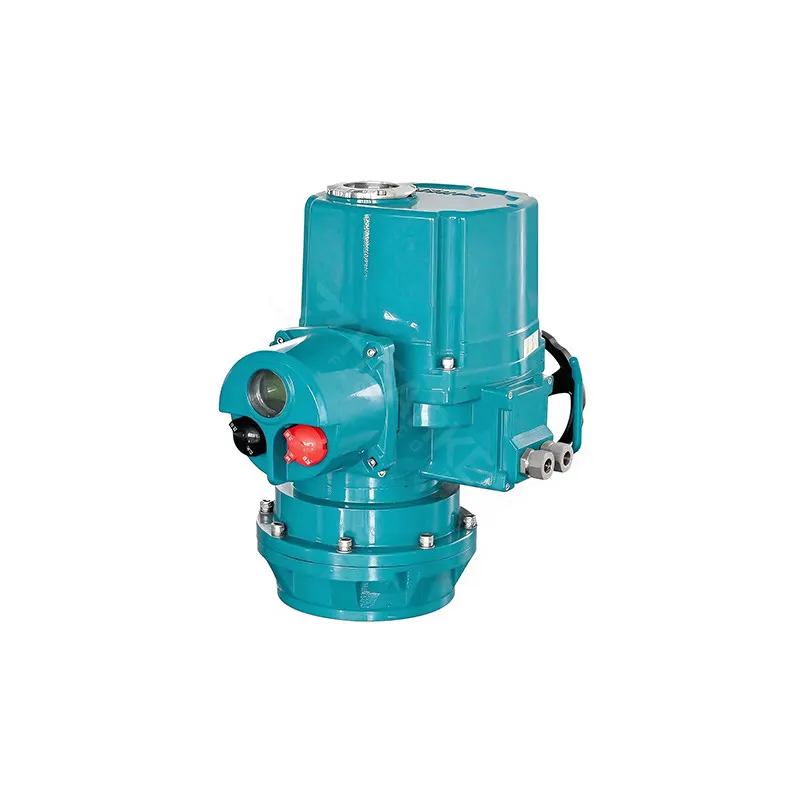
China Multi-Turn Intelligent Electric Valve Actuator


China Multi-Turn Intelligent Electric Valve Actuator
Output Torque: 35 – 3,000 N·m
Speed Options: 18 RPM, 24 RPM (standard); 36 / 48 / 72 / 96 / 144 / 192 RPM on request
Power Supply: 380V AC 3-phase 50Hz (standard); other voltages available
Enclosure Rating: IP68
Explosion Protection: IEC ATEX dIICT4
Position Sensing: Magnetic absolute encoder (no battery)
Fieldbus Protocols: PROFIBUS, FF, MODBUS, HART, ST-RING
Analog Output: 4–20 mA valve position feedback
Display: Graphic dot-matrix LCD (Chinese / English, torque / position / alarm)
Flange Interface: ISO 5210 / ISO 5211; custom available
Certifications: CE, ISO 9001-2008, SIL3, ATEX
Warranty: 18 months from startup
Description
The HMT(R) series multi-turn intelligent electric valve actuator is a new-generation multi-turn intelligent electric actuator engineered for demanding industrial automation applications — power generation, petrochemical, oil & gas pipeline, water treatment, metallurgy, and steel processing.
Built on a large-scale digital integrated control platform, the HMT(R) combines real-time torque measurement, absolute position encoding, and multi-protocol fieldbus integration in a single IP68-rated, explosion-proof enclosure. It is designed to replace legacy multi-turn actuators with a platform that delivers verifiable positioning accuracy, intelligent diagnostics, and full system interoperability.
The HMT(R) multi-Turn intelligent electric valve actuator is available in integrated and separated configurations, with ISO 5210 / ISO 5211 compliant interfaces, selectable drive sleeves, and customizable flange dimensions — supporting direct assembly integration without bracket modification. Full certification documentation including CE, ATEX, and SIL3 assessment reports is available upon request.
Features & Benefits
1. Verified Torque Accuracy — Not Estimated
The HMT(R) continuously measures output torque in real time by detecting motor current, voltage, and magnetic flux through a mathematical model and advanced algorithm. Unlike actuators that rely on preset torque switches, the HMT(R) generates actual torque data — usable for valve diagnostics, predictive maintenance, and SIS documentation.
2. Absolute Encoder — No Battery, No Re-Calibration
Position accuracy is maintained by a magnetic absolute encoder with no battery backup requirement. The encoder retains valve position data through power loss, eliminating the recalibration step on restart that causes unplanned downtime in conventional actuators.
3. Multi-Protocol Fieldbus as Standard
Native support for PROFIBUS, Foundation Fieldbus, MODBUS, and HART — with EDDL and FDT/DTM device descriptions available. The advanced ST-RING topology supports up to 250 actuators per loop over 20 km without repeaters, enabling large-scale distributed installations with a single two-wire fieldbus connection per loop.
4. Non-Invasive Commissioning and Diagnostics
All parameter setting, calibration, and field diagnosis can be performed via hand-held remote or the optional Bluetooth Smart Plus detector (30 m range, wireless charging) — without opening the enclosure. Critical in hazardous areas, high-altitude installations, or confined spaces where enclosure access is restricted.
5. IP68 + ATEX dIICT4 — Designed for Harsh Environments
Double-sealed connection ports block water and gas ingress. The terminal port rotates 90°, allowing cable entry direction to be set on-site to prevent rainwater intrusion regardless of installation orientation. The separated electric actuator variant extends this further — the electrical module can be remotely mounted up to 200 m from the mechanical drive unit for high-temperature or high-vibration installations.
6. Comprehensive Protection Suite
Torque protection, valve position limit protection, automatic phase sequence adjustment, instantaneous reversal protection, power supply phase loss protection, overheat protection, and electric protection — all active as standard. ESD trigger, motor temperature alarm, remote loss alarm, and PST success signal are included in the standard alarm and feedback matrix.
7. OEM-Ready Mechanical Interface
ISO 5210 / ISO 5211 compliant flanges as standard, with Type A (thrust) and Type B (non-thrust) drive sleeves selectable by valve stem configuration. Custom flanges available. The motor installation structure is designed for fast disassembly — reducing service time for OEM partners managing field warranty support.
HMT(R) Series Multi – Turn Electric Actuator
| Model | 380V Actuator 50Hz parameters | Weight | |||||||
| 18 RPM | 24 RPM | ||||||||
| Torque | Power | Rated current | Locked current | Torque | Power | Rated current | Locked current | ||
| HMT035R | 35 | 0.09KW | 0.63A | 1.5A | 35 | 0.12KW | 0.85A | 2.1A | 36kg |
| HMT080R | 80 | 0.18KW | 1.0A | 2.5A | 80 | 0.25KW | 1.4A | 3.5A | 36kg |
| HMT110R | 110 | 0.25KW | 1.4A | 3.5A | 110 | 0.37KW | 1.8A | 4.5A | 37kg |
| HMT200R | 200 | 0.37KW | 1.8A | 4.5A | 200 | 0.4KW | 1.9A | 4.75A | 60kg |
| HMT400R | 400 | 0.55KW | 2.4A | 6A | 400 | 0.75KW | 3A | 7.5A | 62kg |
| HMT600R | 600 | 1.1KW | 4A | 10A | 600 | 1.5KW | 5A | 12.5A | 75kg |
| HMT1000R | 1000 | 1.5KW | 5A | 12.5A | 1000 | 2.2KW | 7A | 17.5A | 172kg |
| HMT1500R | 1500 | 2.5KW | 7.5A | 18.7A | 1500 | 3.0KW | 9A | 22.5A | 172kg |
| HMT2000R | 2000 | 4.0KW | 10.5A | 26.2A | 2000 | 5.5KW | 13.8A | 34.5A | 175kg |
| HMT3000R | – | 3000 | 7.5KW | 17.5A | 43.7A | 175kg | |||
Size Diagram of HMT(R) Series Multi – Turn Intelligent DC Electric Actuators


| Model | A1 | A2 | B1 | B2 | H | H1(Dust cover not included) | D1 | D2 | D3 | CTS | Hand wheel |
| HMT035R | 297 | 374 | 299 | 151 | 280 | 112 | 229 | 160 | 196 | 41 | 305 |
| HMT080R | 297 | 374 | 299 | 151 | 280 | 112 | 229 | 160 | 196 | 41 | 305 |
| HMT110R | 297 | 374 | 299 | 151 | 280 | 112 | 229 | 160 | 196 | 41 | 305 |
| HMT200R | 353.5 | 409 | 321 | 145 | 292 | 112 | 229 | 191 | 196 | 60 | 450 |
| HMT400R | 353.5 | 409 | 321 | 145 | 292 | 112 | 229 | 191 | 196 | 60 | 450 |
| HMT600R | 421 | 439 | 366 | 230 | 326 | 112 | 229 | 230 | 196 | 91 | 400 |
| HMT1000R | 488 | 469 | 366 | 314 | 360 | 112 | 229 | 269 | 196 | 91 | 400 |
| HMT1500R | 488 | 469 | 366 | 314 | 360 | 112 | 229 | 269 | 196 | 91 | 400 |
| HMT2000R | 561 | 469 | 366 | 314 | 360 | 112 | 229 | 269 | 196 | 91 | 400 |
| HMT3000R | 561 | 469 | 366 | 314 | 360 | 112 | 229 | 269 | 196 | 91 | 400 |
HMT(R) Series Multi – turn Intelligent DC Electric Actuators

| Model | OPF | Dsp | Inlet hole | Type A sleeve | Type B sleeve | |||||
| 1 | 2 | h | f | Max thread | h | 1 | 2 | |||
| HMT035R | F10/FA10 | 70/58.7 | M40x1.5 | 2xM25x1.5 | 41 | 3 | 32 | 22 | 3 | 20 |
| HMT080R | F10/FA10 | 70/58.7 | M40x1.5 | 2xM25x1.5 | 41 | 3 | 32 | 22 | 3 | 20 |
| HMT110R | F10/FA10 | 70/58.7 | M40x1.5 | 2xM25x1.5 | 41 | 3 | 32 | 22 | 3 | 20 |
| HMT200R | F14/FA14 | 100/95.25 | M40x1.5 | 2xM25x1.5 | 69 | 4 | 51 | 25 | 4 | 32 |
| HMT400R | F14/FA14 | 100/95.25 | M40x1.5 | 2xM25x1.5 | 69 | 4 | 51 | 25 | 4 | 32 |
| HMT600R | F16/FA16 | 130/127 | M40x1.5 | 2xM25x1.5 | 98 | 5 | 73 | 45 | 5 | 60 |
| HMT1000R | F16/FA16 | 130/127 | M40x1.5 | 2xM25x1.5 | 98 | 5 | 73 | 45 | 5 | 60 |
| HMT1500R | F16/FA16 | 130/127 | M40x1.5 | 2xM25x1.5 | 98 | 5 | 73 | 45 | 5 | 60 |
| HMT2000R | F25/FA25 | 200/152.4 | M40x1.5 | 2xM25x1.5 | 98 | 5 | 73 | 45 | 5 | 60 |
| HMT3000R | F30/FA30 | 230/177.8 | M40x1.5 | 2xM25x1.5 | 122 | 5 | 83 | 45 | 5 | 60 |
Product Application:
Oil & Gas Pipelines
Power Plants (Thermal & Hydro)
Water Treatment Facilities
Chemical Processing Plants
Purchase Guide
Step 1 — Define output torque requirement
Obtain BTO and BTC values from your valve design or testing data, with safety factor applied. Select the HMT(R) model whose rated torque meets or exceeds the higher of the two values. Locked torque is 1.4–2× rated torque and should not be used as the selection basis.
Step 2 — Confirm operating speed
Standard options are 18 RPM and 24 RPM. For applications with water hammer risk or process-critical stroke timing requirements, specify the required RPM at inquiry. Custom speeds (36–192 RPM) are available with confirmed lead time.
Step 3 — Specify drive sleeve type
Type A sleeve (thrust type): for valve stems with significant axial load. Type B sleeve (non-thrust type): for stems where axial force is absorbed by the valve gearbox. Provide stem shaft diameter and mode to confirm sleeve dimensions from the published table.
Step 4 — Confirm power supply and control signal
Standard is 380V 3-phase 50Hz. Specify if your application requires a different voltage, single-phase supply, or DC control. Confirm whether remote control is via discrete on/off, analog 4–20 mA, or fieldbus protocol.
Step 5 — Identify site classification
For Zone 1 / Zone 2 hazardous area applications, specify ATEX dIICT4 variant at order. For high-temperature or high-vibration installations, evaluate the separated electric actuator option (electrical module mountable up to 200 m from the mechanical unit).
Step 6 — Specify gearbox adaption if required
For applications requiring quarter-turn, linear, or non-standard motion conversion, a gearbox adaption module (worm gear / angular travel gearbox, cone/spur multi-turn gearbox, or linear thrust unit) can be integrated. Specify valve type and required output motion at inquiry.
FAQ About Multi-Turn Intelligent Electric Valve Actuator
Q: Which fieldbus protocols are supported natively?
A: PROFIBUS, Foundation Fieldbus (FF), MODBUS, and HART are supported as standard. EDDL and FDT/DTM device descriptions are available. The ST-RING bus topology supports ring networks of up to 250 actuators per host over a maximum loop distance of 20 km without a repeater.
Q: Can the actuator be commissioned without opening the enclosure?
A: Yes. Parameter setting, calibration, and diagnostic queries can all be performed using the hand-held wireless remote — no enclosure opening required. The optional Smart Plus detector adds Bluetooth commissioning (30 m range) with a 3-inch LCD real-time display and offline parameter setting, suitable for confined spaces, high-altitude, or underground installations.
Q: What position feedback signals are available?
A: Multi-turn intelligent electric valve actuator standard configuration includes four relay outputs (R1–R4): two make-on-close contacts and two break-on-close contacts, plus a 4–20 mA analog position output. ESD trigger input, open and close interlock inputs, and monitoring relay output are included on the standard terminal block.
Q: Is partial stroke testing (PST) supported?
A: Yes. PST success signal is included in the standard alarm and feedback matrix. This supports SIL verification requirements without full valve stroke, maintaining process availability during proof testing.
Q: What certifications are available for hazardous area installation?
A: The HMT(R) multi-turn intelligent electric valve actuator carries IEC ATEX dIICT4 explosion-proof certification, suitable for Zone 1 and Zone 2 hazardous areas. IP68 weatherproof rating is standard across all variants. CE and ISO 9001-2008 certifications apply to all models. SIL3 assessment documentation is available on request.
Q: What is the warranty period?
A: All HMT(R) units are warranted against defects in material and workmanship for 18 months from the date of startup. Every unit is factory-tested against applicable standards before shipment.
Q: Do you support OEM private labeling and custom configurations?
A: Yes. OEM options include unbranded units, customer nameplate, custom RAL color coating, and custom flange interfaces. For volume OEM programs we support pre-production engineering review, assembly documentation, and dedicated QC hold points. Contact sales with your annual volume estimate and configuration requirements.
Q: What are standard lead times?
A: Standard specification units: 3–5 weeks. Non-standard speed, custom flange, or ATEX-specified variants: typically 4–7 weeks, confirmed at order. OEM customers with recurring requirements are encouraged to discuss blanket order or safety stock arrangements to reduce response time.