Are you struggling to find a valve that fits your specific air system requirements? Using an incompatible valve doesn’t just waste energy—it can lead to system latency, seal failure, or critical safety hazards.
To ensure precise control regarding on/off switching and directional flow, you need to select Solenoid Valves based on verified technical parameters.
From Hearken Flow, here is your technical checklist for selecting the right pneumatic solenoid valve.
⚠️ SAFETY WARNING & COMPLIANCE NOTE Incorrect selection of solenoid valves in hazardous environments can lead to catastrophic failure. Ensure all electrical components match the specific Zone Classification (Zone 1/2) and Gas Group of your installation site. Always isolate power and pressure before installation.
1. Understanding the Valve Function
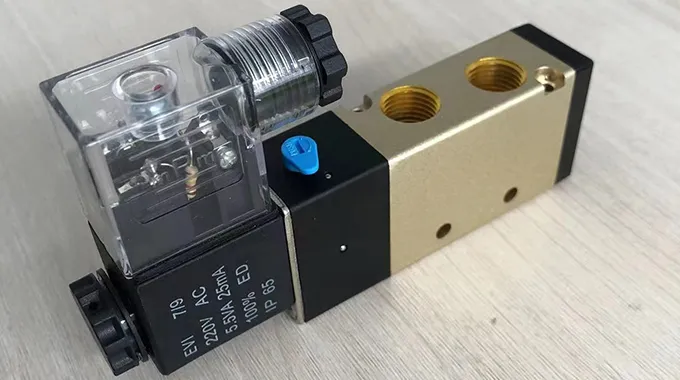
Before looking at specs, define your control needs. Solenoid valves are designed to control the on/off status of air circuits or change the direction of airflow.
- Cut-off/Switching: Stops or starts flow.
- Directional Control: Diverts air to different output ports to drive actuators.
2. Selection Factor: Valve Configuration (Ports & Positions)
Choose the configuration that matches your process logic. At Hearken Flow, we adhere to standard industrial port configurations:
- 2/2-Way: Two ports, two positions (Open/Close). Ideal for simple on/off control.
- 3/2-Way: Three ports, two positions. Typically used for controlling single-acting cylinders.
- 5/2-Way: Five ports, two positions. The standard for controlling double-acting cylinders.
3. Selection Factor: Operation Mode & Pressure Range
Selecting the wrong operation mode is the most common cause of valve failure. Match the valve type to your system’s pressure availability:
- Pilot-Operated Valves (Internal Pilot)
- Pressure Range: 1.5 – 8 bar (Requires minimum pressure differential).
- Characteristics: Designed for fast response frequency. Ideal for systems that require rapid switching cycles with low power consumption.
2. Direct-Acting Valves
- Pressure Range: 0 – 10 bar (Zero differential pressure required).
- Characteristics: Capable of operating from zero pressure. Known for strong reliability, these valves are suitable for driving larger cylinders or applications where pressure may drop to zero.
4. Selection Factor: Electrical Specifications
Voltage instability is a common cause of coil burnout. Hearken Flow coils are engineered with extended tolerance ranges to handle industrial grid fluctuations.
| Parameter | Specification | Engineering Note |
| AC Voltage | AC 220V (Range: 197V – 242V) | Wide tolerance prevents failure during voltage sags or surges. |
| DC Voltage | DC 24V | Standard control voltage. |
| Power | 4.0W / 1.8W (Low Power) | Low power options reduce heat and energy costs in multi-valve manifolds. |
| Insulation | Class F / Class H | Class H allows for higher permissible temperature rise, ensuring longevity in hot environments. |
5. Selection Factor: Seals & Materials (The HNBR Advantage)
Standard NBR seals often degrade due to oil additives or temperature extremes. Hearken Flow utilizes HNBR (Hydrogenated Nitrile Butadiene Rubber) for critical dynamic seals.
Technical Superiority of HNBR:
Thermal Stability: Maintains elasticity in low-temperature environments where standard Nitrile becomes brittle.
Chemical Resistance: Superior resistance to oil additives and hydrogenated environments commonly found in compressed air lubricants.
Result: Extended MTBF (Mean Time Between Failures) and reduced leakage risks.
6. Selection Factor: Safety & Explosion Protection
For installations in potentially explosive atmospheres, select the appropriate protection method. Hearken Flow offers options aligned with industrial safety concepts (referencing standards such as IEC 60079 series principles):
Flameproof (Ex d equivalent):
Concept: The enclosure can withstand an internal explosion without transmitting the flame to the surrounding atmosphere.
Application: High-risk zones where containment is critical.
Intrinsically Safe (Ex i equivalent):
Concept: Limits electrical energy (voltage/current) to levels below what is required to ignite atmospheric gas/dust.
Application: Instrumentation and low-power control circuits.
Standard Explosion-Proof:
Designed for general industrial safety requirements to prevent ignition sources.
7. Installation Type
- Pipe Mounting (Tube): For standalone installation.
- Plate Mounting (Namur/Manifold): For integrating multiple valves into a compact control cabinet.
Summary of Technical Checkpoints
System Pressure: Is the supply consistently above 1.5 bar? (If NO, choose Direct Acting).
Environment: Is there a risk of explosive gas? (If YES, specify Flameproof or Intrinsically Safe).
Power: Is the site voltage stable? (Hearken Flow AC coils handle ±10% fluctuations).
Need detailed datasheets or CAD files? Contact Hearken Flow Engineering Support for specific torque values and flow curves.